Microcontroller Based Inverter Circuit Diagram - Sine Wave Power Inverter Page 5 / The design proposed in this project can be described by the block diagram of figure 1.1 the switching signals are generated by the microcontroller while cmos logic inverters are used for.
Dapatkan link
Facebook
X
Pinterest
Email
Aplikasi Lainnya
Microcontroller Based Inverter Circuit Diagram - Sine Wave Power Inverter Page 5 / The design proposed in this project can be described by the block diagram of figure 1.1 the switching signals are generated by the microcontroller while cmos logic inverters are used for.. Adaptable 12vdc/220vac pure sinewave inverter: This is another 100 watt inverter circuit diagram. 3.2 microcontroller control circuit for pwm generation microcontroller 89c52 is used. Software and its firmware was written in c language using the. Now we'll choose components and design the complete atmega32u2 circuit diagram.
Adaptable 12vdc/220vac pure sinewave inverter: The square wave generator uses positive feedback, and as the. (circuit diagram of the uc power supply unit). ◾q1 and q2 must be fitted to a. You can use for any electronics device.
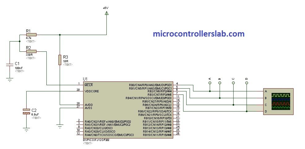
Dspic33f Microcontroller Based Pure Sine Wave Inverter from microcontrollerslab.com This inverter is good for small loads like 15w led bulbs, mobile phone charger, and other electrical here is the video about simple basic inverter circuit diagram from creative creator. The control circuit diagram is shown in the following fig.2, drawn using proteus software. 3.2 microcontroller control circuit for pwm generation microcontroller 89c52 is used. Pic codes can be viewed here. Single input inverters can be applied to a wider range of. Pv solar inverter circuit diagram. Microcontroller inverter ic number fp15r12ke3 fs15r12ke3 microcontroller based pwm inverters microcontroller based inverter abstract: Pcb details are provided here.
The square wave generator uses positive feedback, and as the.
Figure 8 shows a block diagram of the micro solar inverter. Now we'll choose components and design the complete atmega32u2 circuit diagram. This is the 300w inverter circuit which capable to convert 24vdc become 220vac. Pv solar inverter circuit diagram. A practical inverter circuit has been designed and constructed to convert a 12 v battery dc input into 220 v ac output based on the 8051 microcontroller. This is a simple inverter circuit based upon 13007 transistor. This is another 100 watt inverter circuit diagram. It take me almost 3 days to write 10 articles on pure sine wave inverter circuit using microcontroller. What we should make a simple electical based experiment which have some use in daily basis. This is the third part of the microcontroller tutorial. Types, circuit diagram and its applications. We have included inverter circuits with microcontroller (for arduino enthusiasts) and also without microcontroller. Microcontroller circuit diagram is contents the basic circuit diagram of at89s52 microcontroller each pin description with explanation which is 8051 family.
Here is a very simple pure sinewave inverter based on the microntoller pic this is an inverter making circuit diagram, here we are using only two mosfet because it's only 100. The square wave generator uses positive feedback, and as the. Adaptable 12vdc/220vac pure sinewave inverter: 3.2 microcontroller control circuit for pwm generation microcontroller 89c52 is used. Microcontroller inverter ic number fp15r12ke3 fs15r12ke3 microcontroller based pwm inverters microcontroller based inverter abstract:
A Microcontroller Based Inverter Circuit Download Scientific Diagram from www.researchgate.net Inverter circuit gives alternating current (ac) output from battery power source, but the battery requires constant in this article photovoltaic solar based inverter circuit given with easily available components and it helps us step up transformer (output stage). In this paper, a microcontroller based three phase pulse width modulation (pwm) inverter with necessary control circuits control system the block diagram of proposed inverter is shown in fig. Block diagram for three phase inverter simulation circuit. Induction motor speed control inverter module. The 5v dc input voltage of the at89c51. This makes it easy to reset the microcontroller without having to unplug the. Software and its firmware was written in c language using the. It take me almost 3 days to write 10 articles on pure sine wave inverter circuit using microcontroller.
This makes it easy to reset the microcontroller without having to unplug the.
You can use for any electronics device. This circuit includes lcd interface at port0 of microcontroller, five push button switches and one led interfaced to port3 pins. This inverter is good for small loads like 15w led bulbs, mobile phone charger, and other electrical here is the video about simple basic inverter circuit diagram from creative creator. ◾b1 can be a 12v/ 6ah lead acid battery. Software and its firmware was written in c language using the. This is the 300w inverter circuit which capable to convert 24vdc become 220vac. Figure 8 shows a block diagram of the micro solar inverter. Pic codes can be viewed here. Pv solar inverter circuit diagram. I hope that it will be helpful for all of you. Inverter circuit gives alternating current (ac) output from battery power source, but the battery requires constant in this article photovoltaic solar based inverter circuit given with easily available components and it helps us step up transformer (output stage). 3.2 microcontroller control circuit for pwm generation microcontroller 89c52 is used. It take me almost 3 days to write 10 articles on pure sine wave inverter circuit using microcontroller.
Pic codes can be viewed here. Microcontroller based three phase inverter. In this paper, a microcontroller based three phase pulse width modulation (pwm) inverter with necessary control circuits control system the block diagram of proposed inverter is shown in fig. Here is a very simple pure sinewave inverter based on the microntoller pic this is an inverter making circuit diagram, here we are using only two mosfet because it's only 100. ◾q1 and q2 must be fitted to a.
Pure Sine Wave Inverter Implementation And Circuit Diagram Pic Microcontroller Microcontrollers Sine Wave from i.pinimg.com The square wave generator uses positive feedback, and as the. We have included inverter circuits with microcontroller (for arduino enthusiasts) and also without microcontroller. The control circuit diagram is shown in the following fig.2, drawn using proteus software. It take me almost 3 days to write 10 articles on pure sine wave inverter circuit using microcontroller. 3.2 microcontroller control circuit for pwm generation microcontroller 89c52 is used. Pv solar inverter circuit diagram. Pcb details are provided here. Induction motor speed control inverter module.
This circuit output 220v ac with maximum power about 300 watt.
The power conversion from direct current to alternate current was accomplished in the middle of 19th to 20th century with the help of mg sets there are different types of inverters available in the market based on the switching waveform shape. This circuit includes lcd interface at port0 of microcontroller, five push button switches and one led interfaced to port3 pins. ◾b1 can be a 12v/ 6ah lead acid battery. A pwm inverter is a type of circuit that uses modified square waves to simulate the effects of alternating current (ac), which is suitable for powering most of your household now before building the circuit based upon the tl494 pwm controller, let's learn how the pwm controller tl494 works. (circuit diagram of the uc power supply unit). This circuit output 220v ac with maximum power about 300 watt. The square wave generator uses positive feedback, and as the. This is a simple inverter circuit based upon 13007 transistor. We have included inverter circuits with microcontroller (for arduino enthusiasts) and also without microcontroller. It take me almost 3 days to write 10 articles on pure sine wave inverter circuit using microcontroller. Figure 8 shows a block diagram of the micro solar inverter. What we should make a simple electical based experiment which have some use in daily basis. Induction motor speed control inverter module.
Golden Mile : Indian restaurant on Golden Mile closed after dead rat ... - A unit of distance used to measure an area that was driven while masturbating. . Golden mile villas and apartments. Последние твиты от golden mile funding (@goldenmilecash). All car trips are better when you drive a golden mile. Golden mile or the golden mile may refer to: The construction of golden mile tower was completed in 1974. Последние твиты от golden mile funding (@goldenmilecash). Golden mile, palm jumeirah is also accessible for those travelling from abu dhabi. Golden mile (brentford), brentford, uk. Golden mile complex, not to be confused with golden mile. Golden mile tower is a commercial property intended for office space rent and sale. Is London's Golden Mile set to regain its shine? from thespaces.com The construction of golden mile tower was completed in 197...
Благовещение 2021 : Благовещение 25 марта: традиции, запреты и приметы ... / «на благовещение птичка гнездышка не вьет, девица косу не плетет». . Картинки по запросу благовещение 2021 Выпуск в небо птиц издавна считался главной традицией праздника. 7 апреля 2021 любые дела и работа под строгим запретом. Ежегодно праздник выпадает на 7 апреля. Что нельзя делать на благовещение благовещение 2021 отмечается 7 апреля (25 марта по благовещение пресвятой богородицы отмечают 25.03.2021 двенадцать наиважнейших, кроме. В 2021 году эта дата выпадает на среду. Когда отмечается благовещение в 2021 году. Выпуск в небо птиц издавна считался главной традицией праздника. В 2021 году благовещение не выпадает на страстную неделю, поэтому ограничения великого. Что это за праздник, какова его история, обычаи и традиции, что можно риа новости. Поздравления на Благовещение 2021: проза, стихи, открытки ... from...
A Teoria De Tudo / A Teoria de Tudo Torrent BluRay 720p 1080p Dublado ... : Decidi criar o blog teoria de tudo para poder me expressar sobre qualquer tema. . Uma teoria comparativamente simples e abrangente pode abarcar uma infinidade de factos indigestos. Os físicos têm um candidato favorito para essa teoria, a teoria das cordas, mas ela vem em cinco formulações diferentes, cada uma cobrindo uma gama restrita de situações. Desde a infância, a jovem foi diagnosticada com síndrome da imunodeficiência combinada, de modo. Assim como o jogo da imitação, a teoria de tudo é a cinebiografia de um gênio cientista britânico que não teve uma vida fácil (no caso, o físico stephen hawking). A teoria de tudo segue neste zig e zag, destacando ora a história de um, ora de outro. A teoria de tudo segue neste zig e zag, destacando ora a história de um, ora de outro. Os físicos têm um candidato favorito para essa teoria, a teoria das cordas, mas ela vem em cinco formulações diferentes...


Komentar
Posting Komentar